Blog
Sears Garage Door Signal Reverse Engineering
January 4, 2022
Introduction
After seeing my hero Samy Kamkar's research into garage door remotes called Open Sesame, I got interested in software defined radios (SDRs). In particular, I was curious what other items would be vulnerable to replay, interception and other types of attacks. Leading up to some other research (stay tuned!), I dove into my childhood home's electronic garage door opener. This garage door remote is labeled as the Sears Craftsman 139.53708 Garage Door Remote, which was originally manufactured 30+ years ago. Even though this device is old, this post is more about reversing radio signals and recreating the signal ourselves.
In this article, we will dive into the reverse engineering of wireless signals with off the shelf tools and how to launch practical attacks against these wireless systems.
How Does This System Work?
Remote
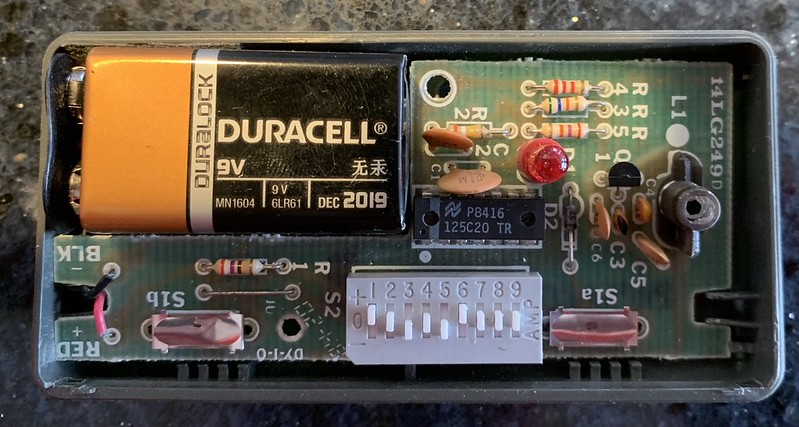
The remote has 9 DIP switches. These are used to configure the secret code that is transmitted to unlock the garage door. Each of these switches has three options: +, 0 and -. Most data transmission is binary in nature. This was interesting since we had a ternary code as opposed to the traditional binary code. All of this information can be seen in Figure 1 above.
The main schematic for this alluded me for a long time, where I initially thought that the main chip was ADC from the P8416. However, with inquiries from Gene Berkowitz and Scott LaBombard after I initially posting this article, I learned the true nature of the device! P8416 indicates the production code: China (P) and the 16th week of 1984. Then, the actual chip part is 125C20. The naming conventions on chips are new to me but I was linked a good resource at chipdocs, which helps quite a bit.
The 125CXXX chip is really a ternary encoder that takes input from the DIP switches. Since the product is a proprietary and owned by Chamberlain, then sold by Sears, there are no public datasheets for this exact product. However, since this is a family of products, there is a schematic for a generic Chamberlain garage door remote that should be fairly similar to our remote. The FCC ID on our target remote returns no information, sadly. Sometimes, venturing off into similar products can be useful for reverse engineering your target if there is no documentation on your target. Good to know!
Syncing
The receiver (door opener) has a button on the side of it. This button is used to sync the receiver with the remote. To reprogram the receiver, this button needs to be pressed then we send our new code from the remote. At this point, the code has been changed on the garage door receiver. This is interesting to me since I expected for a similar DIP switch to be on the receiver as the transmitter but this was not the case.
Signal Analysis
When analyzing signals, there are many components of a signal to consider. Three of the most important are mentioned below:
- Frequency
- Modulation
- Encoding scheme for bits
Going forward, the article will explain my personal methodology for discovering these settings. At the end of the day, it is just reverse engineering though! As with most blackbox reverse engineering projects, utilizing the inputs and outputs of the system is extremely useful for discovering how everything works. All of your previous reverse engineering will apply to this project! The only new skills are the radio/wireless specific skills.
Frequency
The frequency is the oscillation rate of the signal. Practically, in wireless, the frequency is the location of the signal that you are trying to listen to. For instance, the 1090 AM radio station is at the 1090 KHz frequency. The two ways that I find the frequency for a device are via the documentation on the FCC website or staring at a spectrogram until I see a change in it. In retrospective, the FCC website did have the frequency of the device; however, I did not know about the FCC documentation when I started this project a year ago. As a result, the latter approach was taken. A spectrogram is a picture of the radio spectrum with the higher on the y axis translating being a higher amplitude signal and the x axis representing the frequency in use.
From reading Samy's post on garage door remotes, he states that most of them were within the 300MHz-400MHz range. So, this is a good starting point for finding the exact frequency in use. From there, my strategy is fairly simple for finding the frequency:
- Choose a frequency range and tune the radio to this with the spectrogram open.
- Turn on the garage door transmitter.
- Notice if there are any changes with the spectrogram. If there is, then you have found the frequency! Otherwise, go back to step 1 with a different frequency.
In this case, I chose to use the tool GQRX to view the spectrum. For my SDR, I used my HackRF but a receive only SDR, such as RTL-SDR, would have worked fine as well but I simply prefer Inspectrum. The spectrogram view is fairly universal in the SDR world and many other tools support this.
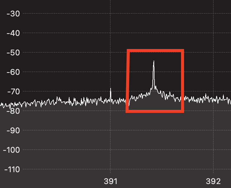
After repeating the steps above for about 10 minutes starting from 300MHz, I found the frequency at 390MHz; the red box in Figure 2 shows the spike in the graph that indicates the frequency. Now that we know the frequency, we can start a more sophisticated analysis of the signal.
Modulation
Modulation is the process of changing a base radio wave to encode information inside of it. In most cases, this happens by changing one or more of three dimensions of a signal:
- Amplitude: The height or intensity of the signal. In the real world, this is the loudness of somebody's voice.
- Frequency: The oscillation rate of the signal. In the real world, this is the pitch of somebody's voice.
- Phase: The degree that the wave that is currently in (think of this as the unit circle). There is not a good real world equivalent for this, unfortunately.
In low power, low noise and low data rate needs, the simplest form of amplitude modulation is used: On-Off Keying (OOK). Simply put: if there is a 1, then turn on the signal. If there is a 0, then turn off the signal. Since this was a simple garage door remote, I assumed that OOK was being used.
For attempting to identify the modulation of a signal, I turn to spectrograms once again. Figure 2 works well for a starting point for figuring out the modulation mode. Since the GQRX spectrogram only had a single, thin line for the signal, it is safe to assume that the encoding was NOT using frequency or phase to encode the data. If it was using a digital frequency modulation, then there would be 2 or more distinct spikes for the frequencies being used. If it were using phase, then there would be a much larger bandwidth and the Spectrogram view would be more round as well. For more information on what modulation types look like, view the Signal Identification Wiki.
Besides GQRX for a basic overview of the signal, we need some other tools for a more fine grained view of the signal. Both Inspectrum and Universal Radio Hacker are awesome tools for exactly this. For simply viewing the signals, I prefer Inspectrum because of the automatic decoding tools and simplicity of it. Let's open up our signal in Inspectrum!

In Inspectrum, the left-right axis is the time, the vertical axis is the frequency and the color of the signal is the amplitude. From looking at the recording in Inspectrum, all of the green lines are the same on the vertical axis. This indicates that the frequency of the signal is consistent; this rules out both frequency and phase modulation as a result. Since the only item changing is amplitude (thick green line is the ON), this must be a form of amplitude modulation. To be more precise, only signal ON or signal OFF is being used. This is a specific type of amplitude modulation called On-Off Keying (OOK), which was explained before.
Encoding Scheme
How Long Is a Symbol?
At this point, we know the modulation being used is OOK. It is time to find out how the bits are being conveyed and what they actually mean.
In Figure 3 above, there are several differently sized pulses of ON. To find the symbol rate, we need to calculate the amount of time the smallest pulse in the signal takes. The symbol rate is important to know because we need to be able to differentiate between a 1 and a 11. In this case, the symbol rate was 1 microsecond (ms), which was measured by the signal on the far left of Figure 3. In Figure 3, there is a symbol of ON (the thick green line), 3 symbols of off, 1 symbol of on... and so on. Once we know the symbol rate, we can decode the raw 0s and 1s from the OOK signal.
From OOK to Symbols
Now, we know the symbol rate as 1 millisecond. Since we know how long a single OOK pulse is, we can find the raw symbols from the transmission. Again, we will use our friend Inspectrum to help with this!
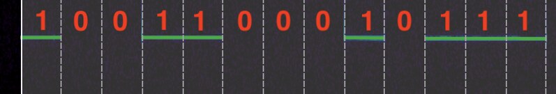
Inspectrum has an amazing feature that allows you to overlay a grid to compare between symbols. This can be seen in Figure 4 with the area between the vertical dashed lines representing a symbol. The locations with a green line in Figure 4 represent an ON for the OOK signal. The blackness between the green lines represents a 0. For example, the first box has a green line so this is a 1. The second two boxes do not have the green line, making this a 0. This continues until the end of the signal.
To make this even easier, you can use a threshold graph with a chosen modulation to have Inspectrum decode the data automatically! The OOK symbols shown above in Figure 4 are 1001100010111. If you look at the dividers, this becomes easy to see.
If you go through the process mentioned above with an entire period of symbols, you will get the full raw OOK transmission. Audacity could have been used to do a lot of similar analysis as well. To get plenty of different samples, we will we change the DIP switches so that the data transmitted varies. Six examples of signals and their raw OOK output are shown below:
ALL +:             10011001100110011001100110011001100110001000

ALL 0:             10001000100010001000100010001000100010001000

All -:             10111011101110111011101110111011101110001000

+,0,-,0,0,0,0,0,1: 10011000101110001000100010011000100010001000

+,0,-,0,+,0,-,0,+: 10011000101110001001100010011000101110001000
From Symbols to Bits
The information above is the raw symbols from the OOK signal with the symbol rate from the previous section. But, what do these have to do with our +, 0 and -? With enough patience and pattern matching skills, we will figure out how each of the bits is represents (and other format specifications of the packet) from the raw OOK signal from above.
To start this process I create a hypothesis about how the data is encoded and try this out on several recordings. If my idea is correct for all of the outputs, then the encoding scheme hypothesis must be correct. Otherwise, it is time to go back to the drawing board with a new idea. The more we understand the system and how radio transmitters are designed, the easier it will be to decode it. There are a couple of tendencies that are good to know about:
- Most transmissions have a preamble or sync word. This is one or more bytes that tells the receiver to wake up and when to start listening for actual data. In this case, the packet does not have one though.
- A single bit will likely be spread into multiple symbols of transmission. This is for redundancy (making mistakes easy to correct or detect) and several other reasons. This (multiple symbols to bit) is especially true in this case since we have a ternary code.
There is one thing that makes this much easier to reverse engineer though: the switches. Modifying the switches gives us direct control over the bits being sent over the air! Since our goal is to figure out how the DIP switches map to actual radio signals, we can set the DIP switches one way then check how these radio signals actually look like once we send them. For instance, we could set the switches to be all +'s to uncover the encoding scheme of a +. To start with, I did exactly this and took a recording with all +'s, all 0's and all -'s. Since we know a large amount of the inputs going into the system (less unknowns to handle), we can decipher the bits represented in terms of symbols fairly quickly.

Now, back to the pattern matching... If you look at the raw OOK bits above in the all 0 code on the DIP switches, you will notice that there is a continuous pattern: 1000-1000-1000.... The Inspectrum view can be seen in Figure 5 above as well. Since this stream is continuously in the signal, this must be how the OOK signal represents a 0! We can do the same thing with + and - to find the bit patterns for these as well. The output of this is shown below:
- +: 1001
- 0: 1000
- -: 1011
Full Packet Set Up
There are only 9 switches on the transmitter. With 4 symbols per bit, this adds up to 36 total symbols of data being sent. However, when we look at the signal, there are 44 symbols being sent. What are the other two for? In a plot twist, they are ending sync bits. The end of the packet must be followed by two 0's (1000) in order for the packet to complete. The reason we know this is at the ending is because the first 2 bits change whenever we change the DIP switches while the ending 00 remains the same regardless of the configuration of the DIP switches. It should be noted that if these two bits are not sent, then the packet will not be accepted.
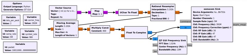
Additionally, I wrote a GNU Radio Script via the GUI (companion) to create an OOK signal with the bits that I wanted to send. Initially, the raw data that I wanted to send did not work. From playing around with different settings and changing some of the bits, I found a few other things that had to be in order:
- The code has to be sent correctly 5 times in a row for the garage to open.
- An OFF (no signal) of 24 symbols needs to be held between attempts.
Although the full explanation of the OOK transmitter is out of scope for this article, the block diagram created in GNU Radio for transmission is shown below. The Github Repository has the complete code for this as well.
Small Encoding Problem
At this point, we are fairly confident in how the combination of symbols makes up a single bit of data and the trailing 2 bits at the end. However, the entire bit stream was not correct. Whenever I got to bit 7, my encoding scheme ideas would fall apart. For instance, let's take an example from above: +,0,-,0,+,0,-,0,+.
According to the chart of mappings from bits to symbols, this should translate to 1001-1000-1011-1000-1001-1000-1011-1000-1001. However, if you look at the raw output, you will notice that bit 7 is wrong! Instead of 1011 for - it is 1001. Additionally, bit 9 is also wrong; it is 1011 instead of 1001. Since this made zero sense to me, I spent a few days coming up with alternate encoding schemes for the bits. 5 symbols to a bit, header instead of a footer and many other ideas were thought about but none of them worked. So, what could this possibly be?
The Curse of the Sync
After having this problem, I placed all of my decodings into an excel spreadsheet for easy analytical comparisons. I have found that a change in the representation of data helps substantially with pattern matching problems such as this one. In this sheet, I noted all of the wrong bits from start to finish. At this point, I realized a pattern: the only WRONG bits were 7 and 9. In my previous analysis, once I saw bit 7 being wrong, I would go back to the drawing board with more ideas. Then it hit me...
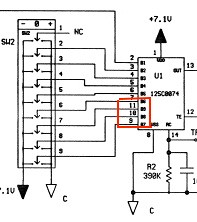
Bits 7 and 9 were never wrong. Instead, 7 and 9 were switched! From our previous example of +,0,-,0,+,0,-,0,+, the transmitter would send 1001-1000-1011-1000-1001-1000-1001-1000-1011 but our expected signal is 1001-1000-1011-1000-1001-1000-1011-1000-1001. If we switch bits 7 and 9, we get our expected signal! According to Scott LaBombard (who had done an analysis on a similar product), this happened on his remote as well. The schematic for a similar part demonstrates that the 125C encoder has the first few switches lined up in order (2-8). However, the final three (9-11) are lined up in reverse order; this can be seen in Figure 7 in the schematic diagram. This was likely done for circuit simplicity but may have been "security by obscurity" back in the 90s as well. Still interesting to get to the bottom of this after only passively observing this with no real explanation.
You may be wondering "If the bits are switched on the transmitter, how does the receiver consume this data then?" When we set up the code via the sync method, it listens for the new code required to open the door. As a result, the DIP switch ordering does not matter as long as the transmitter is consistent with the bit order being sent to the receiver. The bad mix-matched line job of the manufacturer does not matter for the usage of the remote but it made the reverse engineering much more confusing!
Attacking the Garage Door
Now that we understand how the signal works, what can an attacker practically do? To me, there are two main attacks to worry about: replay and brute forcing the code.
Replay
A replay is exactly what it sounds like: recording a signal and resending the recorded signal. Since the garage door has a stagnant code, this will open the garage door as if the real remote was sending the data. Practically, this could be done by having a Raspberry Pi or Arduino set up to listen for all data on a specific frequency. When this frequency is hit with a high powered signal (RSSI) from the transmitter, the recorder would be triggered for a few seconds to record the signal. Then, later on, an attacker could pick up the device and replay the signal to open the door.
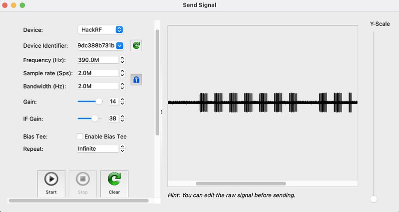
This attack is quite simple in theory. Record a signal and replay it. However, the settings within the tools being used matter. When using replay attacks with Universal Radio Hacker (URH), set the gain settings to be extremely high to compensate for the lost power from the original transmission. The other issue that I have encountered is that the software and format of the recording do matter. For instance, recordings from GQRX do not work in URH very well. If I'm using a replay attack, I usually record the signal in URH then transmit the signal with high gain settings in the same tool.
Brute Forcing the Code
To launch this attack, we need to have a programmatic way to change the bits being sent in the signal. I personally have trouble using GNU radio and the companion to do useful things. So, I modified the project OOK transmitter on Github to actually send these bits 1 by 1. The input for the program is a vector or list of numbers that can be pre-computed as the input or modified on the fly. Since we know ALL of the patterns for +, - and 0, we can calculate sequences that would work for this program using combinatorics. The code for my modification is linked here.
To see how feasible this attack is we will do some math!
- A symbol takes 1 millisecond to send.
- There are 64 symbols in a period/packet if you include the required wait time.
- The same code needs to be sent properly 5 times to open the garage door.
- There are 3^9 or 19683 possible codes. This is a combinatorics problem with 3 possible values (+, 0, -) and 9 different switches.
6298560 milliseconds= 1 * 64 * 5 * 19683or about 104 minutes.
Unfortunately, I could not find any way to speed up this attack. The Open Sesame Attack abuses the fact that some of the garage door receivers work as a shift register, making it possible to check multiple codes at once via a De Bruijn Sequence. Since the code MUST be sent 5 times correctly in a row and the mandatory footer at the end, this attack did not work for this garage door remote. For a garage door remote made prior to the popularity of SDRs, this actually is not bad security!
Below is a video of myself opening my parents garage door using the GNU Radio code shown above. An uncommented version of the video can be found here as well. Please, enjoy the madness of SDRs!
Remediation
The brute force attack is fixed by having a larger search space. Instead of only having 9 bits, using 15+ bits drastically increases the amount of attempts for brute force the code. For instance, 3^15 is 14,348,907 possible codes. Using the same math from above to calculate the full length of the attack, it would take 53 days to brute force the code. This is much better security than before.
The replay attack is a much more complicated problem to fix. My initial thought was to encrypt the data and use a nonce (number used once) to ensure that the data cannot simply be replayed. Once the nonce has been used, the receiver would never accept that value again. The encryption ensures that the key code is kept confidential while the nonce ensures that the encrypted data cannot simply be passed along. Practically, the transmitters and receivers are low power and low storage, meaning nonce storage and the power required for encryption makes these difficult to use.
Instead of the above solution, a rolling code is implemented instead. As a replacement for the same code being sent, the transmitter and receiver are synced up on an algorithm that allows a seemingly random number to be sent. Once this happens, both the transmitter and receiver go to the next number in the algorithm, making the replay attack no longer possible. This can be defeated via RollJam attacks or by figuring out the state of the algorithm from previous recordings.
Conclusion
Wireless signals are all around us. At my parents house alone, I noticed that the thermometer, garage doors, dog electric fence and many other things are transmitting signals all the time. Are these secure? It turns out that many are vulnerable to trivial replay or spoofing attacks and no one has noticed. In the future, I hope to post several more blogs about reverse engineering custom wireless devices such as the Sears Garage Door opener done in this post. Major S/O's to the people who emailed me after the initial post to help me learn more about the system. If you have any questions or comments about the content, please feel free to reach out to me! Cheers, from Maxwell "ꓘ" Dulin.